BOM
BOM Cart()
 English
 Russia
 Korean
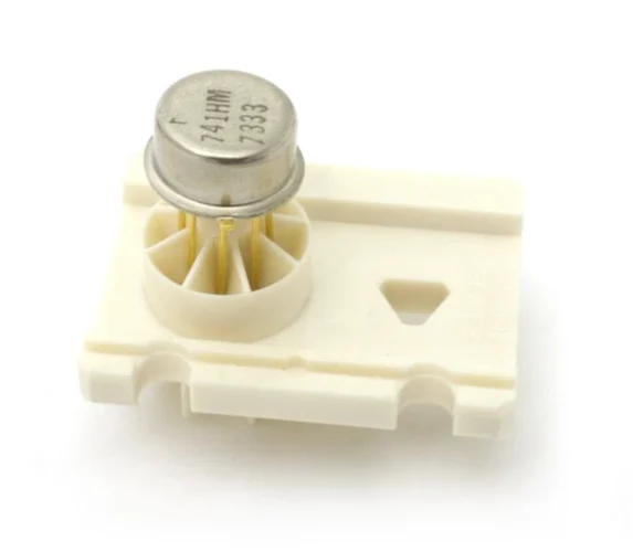
Released in 1968 by Fairchild, the µA741 brought internal frequency compensation and short-circuit protection to the op-amp world.
By the mid-1960s, op amps were no longer in the realm of vacuum tubes and discrete transistors. Bob Widlar’s early designs for Fairchild Semiconductor—particularly the μA702 and μA709—had proven that analog building blocks could be integrated on a single chip. But they were finicky. The 709, in particular, required external compensation capacitors and was prone to oscillation unless carefully laid out. It was functional, but not exactly friendly.
That changed in 1968, when Dave Fullagar, working at Fairchild, introduced the µA741. His design took the two-stage, op-amp structure and added an on-chip compensation capacitor, something that was revolutionary for the time. That simple inclusion meant designers no longer needed to tailor external networks just to make their amplifier stable. Suddenly, you could drop the µA741 into a schematic, close the loop, and expect it to work.
The µA741 operational amplifier, designed in 1968. Image used courtesy of Dave Fullagar via Computer History Museum
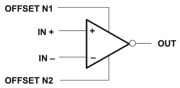
But Fullagar didn’t stop there. The 741 also included short-circuit protection, input protection diodes, and offset-null pins. It ran from a wide supply range (typically ±15 V), and it could drive modest loads directly. In effect, the µA741 took the op amp out of the lab and into mass production. It set the template for what a “general-purpose op amp” should be.
Thinking in Loops
The µA741 used a classic two-stage, op-amp topology that would become textbook material for decades. A differential NPN input pair forms the first stage, feeding a gain stage with an active load and a Miller-compensated dominant pole. A 30-pF internal capacitor (one of the earliest uses of silicon-nitride capacitors) is connected between the first and second stages, setting the amplifier’s bandwidth and ensuring unity-gain stability.
Simplified schematic of the µA741. Image used courtesy of Texas Instruments
The output stage is a class-AB push-pull emitter follower, capable of modest sourcing and sinking, with internal current limiting that protects against shorts to ground or rail. This made the 741 unusually robust for the era.
Inputs are not rail-to-rail, nor is the output. With a typical ±15-V supply, the input common-mode range and output swing are both about ±13 V, requiring about 2 V of headroom on either side. The input offset voltage was respectable for the time (~5 mV max), and the input bias current sat in the microamp range, which, again, was good enough for a general-purpose analog front-end.
Engineers quickly learned the habits the 741 encouraged:
- Add a balancing resistor to the non-inverting input to match input bias currents.
- Use the offset-null pins (pins 1 and 5) to zero the output in DC-sensitive applications.
- Expect a modest slew rate (~0.5 V/μs) and a 1-MHz, gain-bandwidth product.
In exchange for those limits, the 741 provided predictable, loop-stable gain in a single part number.
The Go-To Op Amp for Decades
For decades, the µA741 was the go-to op amp for integrators, filters, buffers, summing amps, and slow control loops. It showed up in analog synths, process controllers, power supplies, and countless textbooks. Its simplicity meant it was both easy to teach and easy to use.
That said, the 741 shows its age in modern designs. It isn’t rail-to-rail, and it struggles at low supply voltages. With a slew rate of 0.5 V/μs, it’s not suitable for fast audio, video, or RF work. Its input noise (~20 nV/√Hz) and bias currents (hundreds of nA) make it unsuitable for precision instrumentation. And with a 1-MHz GBW, it tops out quickly in high-gain configurations.

Fairchild's µA741 op amp. Image used courtesy of Mark Richards via the Computer History Museum
Still, in ±12-V or ±15-V analog domains, where bandwidth is modest and power isn’t mission-critical, the 741 can still be the right tool, especially when ease of use matters more than performance. And it lives on in CMOS variants, hobbyist kits, and retro analog gear.
But perhaps the µA741’s biggest legacy isn’t what it did but rather what it taught. It standardized the op-amp abstraction, a virtual short between inputs, infinite open-loop gain, and feedback as king. And it taught generations of engineers to build stable analog systems by closing the loop and letting the compensation do its job.
Were you around when the µA741 broke into the analog scene? Tell us about your experience in the comments below.

EA-CHIP INDUSTRY CO., LIMITED
-
Tel
+86 180 2549 2789 -
Wechat