BOM
BOM Cart()
 English
 Russia
 Korean
Rohm's new brushed DC motor drivers may help designers balance reuse, protection, and ultra-low standby power in compact motor stages.
Rohm’s latest brushed DCmotor drivers, the BD60210FV and BD64950EFJ, target a design problem that keeps showing up in modern appliances: you want a motor stage that can be reused across multiple product variants, but you also need it to sip power when the system is “off” without compromising protection and control features when it’s running.
Rohm claims its the new motor driver ICs are an "energy-efficient" solution for white goods.
Both ICs are built around integrated H-bridge outputs, with standby current specified down to 0 μA typical and 1 μA max under their respective standby conditions. That’s an important detail in equipment that spends most of its life plugged in and waiting. In that context, shaving mA from a motor stage that’s idle 23 hours a day can be as meaningful as improving efficiency during a short actuation event.
BD60210FV: One Package, Multiple Load Types
The BD60210FV (datasheet linked) integrates two H-bridges that can be configured to drive two brushed DC motors, a single bipolar stepper motor, or up to four solenoid loads. That’s the sort of flexibility that lets a single PCB design cover multiple SKUs—say, a product family that uses either dual small motors or a stepper-driven mechanism, without swapping the driver architecture.

Block diagram of the BD60210FV.
Rohm also gives designers choices in how they control it. The device supports direct PWM control and provides four selectable drive/interface modes that determine how many MCU pins are required and how the outputs are arranged. At its simplest, it can be run as a conventional four-pin interface. It can also collapse into a two-pin interface mode, which is useful if you’re short on GPIOs. There’s a parallel-bridge mode for combining outputs when you want more current capability for a single load, plus a half-bridge mode that can be handy for certain actuator topologies.
Those modes are selected using a combination of a mode pin and an input state, allowing the same silicon to switch between “feature-rich” and “pin-efficient” designs with minimal changes. This can reduce both PCB churn and firmware divergence for designers who build a base control board and then spin a few variants.
Typical application circuit using the BD60210FV.
In terms of power stage capability, Rohm designed the BD60210FV for lower-voltage systems, with an operating supply range of 8 V to 18 V and output current ratings suitable for small motors and actuators. Rohm specifies 1-A continuous per phase with a 4-A peak rating, and a typical combined high-side plus low-side ON resistance of 0.95 Ω. It also includes stepper-specific support for full- and half-step sequences in bipolar stepper configurations.
BD64950EFJ: Higher Voltage and Current
Rohm built the BD64950EFJ (datasheet linked) for applications that need more voltage headroom and higher continuous current. It integrates a single H-bridge rated for up to 40 V, with 3.5-A continuous output current and a 6-A peak rating. It’s still designed to be driven directly by a microcontroller using a PWM, but its distinguishing feature is its built-in PWM constant-current control.

Block diagram of the BD64950EFJ.
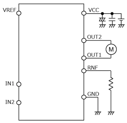
Constant-current control becomes useful as soon as you care about stall conditions, torque limiting, or repeatable actuator behavior under varying loads. BD64950EFJ implements this by using a current-sense resistor connected to an RNF pin and a VREF input that sets the limit threshold. The chip then chops the drive using a fixed off-time scheme when the sensed current reaches the programmed limit.

Typical application circuit using the BD64950EFJ.
Where Rohm has clearly tried to reduce external “fixup” components is around noise and current-sense behavior. The datasheet describes a built-in spike noise cancel function that introduces a minimum on-time (a cancel time) to avoid false triggering from current-sense spikes that occur right as the output switches. The practical benefit is that designers can often avoid adding an external RC filter on the sense path just to keep the comparator stable, which saves parts and board area while improving repeatability across builds.
Changing the Design Conversation
The “0 μA typical, 1 μA max” standby spec reads like marketing until you consider how often motor drivers sit powered but inactive. Many appliances keep a low-voltage rail alive for sensors, wake circuitry, or network connectivity, even when the motor itself is idle. A motor driver that leaks mA in standby can be one of the larger contributors to always-on consumption, particularly in designs with multiple motor channels across a platform.
By essentially eliminating standby current, these ICs let designers focus their standby-optimization efforts where they matter. The BD60210FV’s explicit power-save pin makes it simple to force a known low-leakage state. The BD64950EFJ achieves its standby condition through control inputs, yielding a similar outcome in systems where the MCU can guarantee defined logic levels during sleep.
Just as importantly, both parts reduce the supporting circuitry that often grows around a motor stage: integrated H-bridges, built-in logic pull-downs, fault reporting, protection blocks, and (in the BD64950EFJ’s case) current limiting with spike-noise handling. Fewer external components typically mean fewer failure points, less layout risk, and easier reuse of designs across products.

EA-CHIP INDUSTRY CO., LIMITED
-
Tel
+86 180 2549 2789 -
Wechat